Derive The Equation And Transformation Matrix For Producing Parallel Projection On 2D Viewing Plane And Also Explain Orthographic And Oblique Projections
• Parallel projection methods are used by engineers to create and working drawing of an object which preserves its true value.
• In the case of parallel projection the rays from an object coverage at infinity, unlike the perspective projection where the rays from an object converse at infinite distance.
• Parallel projection can be categorized according to the angle that projection of direction plan.
Transformation of Parallel Projection
• Parallel projection (are also known as orthographic projection) is projections into one of the coordinate plans.
x = 0, y = 0 and z = 0
• The standard transformation parallel projection into the xy plane (i.e = z = 0 plans) is:
z = x' = x
y' = y
z' = 0
• In matrix form:
Orthographic Parallel Equation
• When the projection lines are perpendicular to the view plane, we have an orthographic parallel equation.
• Orthographic projections are most often used to produce the front, side and top view of an object.
• Engineering and architecture drawings commonly used in orthographic projections.
• Because length and angle are accurately depicted and can be measure from the drawing.
• Transformation equations for an orthographic parallel projection are straight forward.
• Figure of orthographic parallel projection is given below:
Oblique Parallel Projection
• An oblique projection is obtained by projecting points.
• Along parallel lines that are not perpendicular to the projection plane.
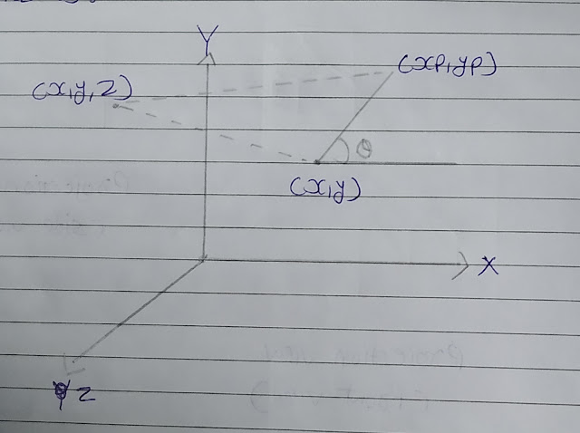
• Coordinates of oblique parallel projection can be obtained as:
• As shown in the above figure (x, y, z) is a point at which we are taking oblique projection (x, y), (y, p) on the view plane is an orthographic projection of (x, y, z).
xp = x + ∠cosθ
yp = y + ∠sinθ
∠ = z / tanx
so, tanx = z / ∠
Cohen Sutherland In Computer Graphics
3-D Rotation In Computer Graphics
Comment your views on this Article :)


No comments
Comment your views on this article